A VNA (vector network analyser) is an invaluable piece of test equipment for RF (radio frequency) work. Until quite recently a VNA was outside the reach of the average radio amateur or experimenter, with professional kit typically costing over £10k. Last year a cheap two-port VNA known as the NanoVNA became available from manufacturers in China. Typically selling for around $50, the open source design was capable of operating up to 300MHz. There are now several different versions around including the NanoVNA V2 (saa2) which operates up to 3GHz, and is the subject of this review.
What is a VNA?
A VNA is essentially an RF signal generator combined with one or more receivers. A two-port VNA can operate in two modes, single port or two port (thru). In two port mode (S21) the signal generator is connected to one port and the receiver is connected to the other. A network, such as a filter, can be connected between the ports and the performance in terms of amplitude and phase can be characterised over a range of frequencies. In single port mode (S11) the same port is used for both the signal generator and receiver, and the receiver measures what is reflected back from the load connected across the port. A typical application for this would be measuring the impedance of an aerial over a range of frequencies.
The NanoVNA V2 (S-A-A-2)
I got my NanoVNA from Banggood in China. It arrived fairly quickly and luckily I did not have to pay any import charges. I opted to buy it with the accessory kit and laser-cut case, as shown in Fig.1. I suspect the unit is a ‘clone’ rather than from the designer’s authorised manufacturer. Because the design is all open-source, anyone can make and sell these units.
 |
| Fig.1 - NanoVNA V2 kit |
After checking that the unit powered up okay I set about assembling it into the case. Some fixings and O rings are provided so that the SMA connectors can be fixed to the panel for strain relief. Getting this right was quite fiddly. The kit is supplied with M3 panhead screws which replace the screws holding the two PCBs to the spacers. Unfortunately, by using the replacement screws to hold the case together, the PCBs are no longer being held tight against the spacers. After fitting the case I initially found that touch screen functionality no longer worked. I discovered that, although the screws were by no means tight, the display was being affected by the plastic case pressing on the screen. This was resolved by loosening the four screws. The case is poorly designed, so at some stage I will need to re-engineer this, perhaps by putting additional M3 spacers between the PCBs and the case panels. The cased unit is shown in Fig.2.
 |
Fig.2 - NanoVNA V2 fitted in its case |
Before making any measurements the unit should be calibrated over the frequency range you intend to use it. It is easy to set the start and stop frequencies, either individually or by setting a centre frequency and a span. The accessory kit includes three calibration loads: short circuit; open circuit; 50 ohms (which actually measures 50.39 ohms at DC). It is simple to perform the calibration with each load in turn and calibration data can be saved in memories (including instrument configuration) which can be recalled at a later date.
The instrument offers 11 different display formats including return loss, VSWR, impedance and Smith chart. I set it to measure the impedance and VSWR on a small helical whip antenna (Fig.3). It shows resonance around 800MHz.
 |
Fig.3 - VNA Impedance and VSWR plot created using NanoVNA-QT |
The Software
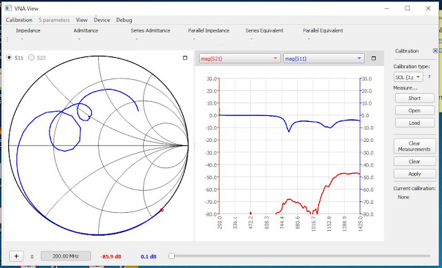
The ‘official’ software is NanoVNA-QT, which is available for Windows, MacOS and Linux. The software allows the unit to be operated using a PC (via the USB cable), which some users may prefer due to the fairly small display (2.8”) on the unit itself. Other popular options are NanoVNA Saver (multi-platform) and NanoVNA WebApp (Android). I opted to try NanoVNA-QT as this is described in the NanoVNA V2 manual (Ref.1). The software can be downloaded from github (Ref.2). This includes a device driver for the USB, but I did not need that for my PC. For Windows you just run the .exe file provided. The NanoVNA-QT GUI is shown in Fig.4. The software worked flawlessly and allowed me to operate the VNA entirely from the PC. Note that the PC software cannot access any calibration data that may already be stored on the VNA (when operating it without NanoVNA-QT). It is necessary to calibrate the unit within NanoVNA-QT before making measurements.
 |
| Fig.4 - NanoVNA-QT graphical user interface (GUI) |
Conclusions
So far I am quite impressed with this little unit and can see it getting a lot of use in my electronics lab. The optional laser-cut case is poorly engineered, but I believe other enclosure options are available, especially if you own a 3D printer.
I am planning to write more articles on VNA measurements, incorporating some RF theory.
References
- S-A-A-2 User Guide UG1101 (Jan 2020), OwOComm. Available from https://raw.githubusercontent.com/nanovna/NanoVNA-QT/master/ug1101.pdf
- VNA-QT software download: https://github.com/nanovna/NanoVNA-QT/releases
- Getting started with the NanoVNA. Available from https://hexandflex.com/2019/08/31/getting-started-with-the-nanovna-part-1/
Disclaimer: This is my personal blog. Views expressed in my posts are my own and not of my employer. The information provided comes with no warranty. I cannot be held responsible for the content of external websites. Any practical work you undertake is done at your own risk. Please make health and safety your number one priority.

Comments
Post a Comment