As mentioned in my previous posts, SDR-Console has no built-in provision for Morse keying. Therefore I have built an 800Hz keyed sinewave oscillator which modulates the SSB transmitter, thus producing a CW signal.
If an SSB (single sideband, suppressed carrier) transmitter, set on upper sideband, is modulated with a frequency fm, it will produce a signal of fc + fm, where fc is the carrier frequency (in this case, suppressed). If both transmitter and receiver are set to the same 'dial' frequency, a tone of frequency fm will come from the receiver. Of course, the modulating signal must be a pure sine wave otherwise a band of frequencies will be produced rather a single CW signal.


Note that the circuit described here could be used to operate CW on any SSB-only transceiver, by connecting it to the microphone input. Just be careful not to overdrive the transmitter.
My Adventures in Satellite Communications - Part 4 (putting it all together)
Disclaimer: This is my personal blog. Views expressed in my posts are my own and not of my employer. The information provided comes with no warranty. I cannot be held responsible for the content of external websites. Any practical work you undertake is done at your own risk. Please make health and safety your number one priority.
If an SSB (single sideband, suppressed carrier) transmitter, set on upper sideband, is modulated with a frequency fm, it will produce a signal of fc + fm, where fc is the carrier frequency (in this case, suppressed). If both transmitter and receiver are set to the same 'dial' frequency, a tone of frequency fm will come from the receiver. Of course, the modulating signal must be a pure sine wave otherwise a band of frequencies will be produced rather a single CW signal.
CW Tone Generator
The full circuit is shown below. It is based on a design by Eamon Skelton which is in the RSGB Radio Communication Handbook (Browne & Stevens, 2016). I have modified the design to make it into a stand-alone, battery-powered unit suitable for use with a PC-based software-defined radio (SDR). The op-amp is configured as a phase shift oscillator, which is buffered by the JFET Q1. MOSFET Q2 acts as a switch, controlled by the Morse keying. When there are not ‘dits’ or ‘dahs’ the MOSFET is switched on, thus shorting-out the audio signal. If you build this you make need to tweak the value of R15 to get the best compromise between signal amplitude, distortion and reliability of starting. The two 33 ohm resistors, R16 and R17 were needed in order for my laptop PC to recognise that something was plugged into the audio jack. The resistors simulate the load presented by typical headphones. To save the bother of a power switch, the battery is connected by plugging the key jack in.
Construction
The prototype was assembled on a homemade single-sided PCB. The CAD artwork was transferred to the copper-clad board using the laser printer method (see DIY Prototype PCBs). For the audio connection to the PC I cannibalised an ‘AUX’ cable.

Performance
My prototype gave an output of around 40mV rms at 800Hz. The plots below show the frequency spectrum of the modulating signal, as shown on the SDR-Console software. Plot 1 shows the 800Hz fundamental, the 2nd harmonic (36 dB down) and 3rd harmonic (50 dB down). It is possible to further attenuate the harmonics using the digital filtering within SDR-Console. Plot 2 shows the modulation signal after application of a custom bandpass filter centred on 800Hz. Plot 3 shows the spectrum with the ‘key up’. There is still a tiny bit of signal coming through the switch due to the finite on-resistance of the MOSFET. However, at -56 dB it is negligible.
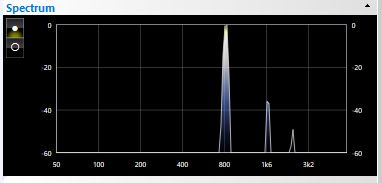 |
| Plot 1 |
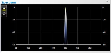 |
| Plot 2 |

| Plot 3 |
Conclusions
The tone generator provides a practical solution for operating CW using the ADALM PLUTO radio with SDR-Console software. I am currently using it to work CW stations through the QO-100 geostationary satellite (see previous post).Note that the circuit described here could be used to operate CW on any SSB-only transceiver, by connecting it to the microphone input. Just be careful not to overdrive the transmitter.
My Adventures in Satellite Communications - Part 4 (putting it all together)
Reference
Browne, M and Stevens, M (2016). Radio Communication Handbook. RSGB, Bedford.Web Resources
SDR-Console - https://www.sdr-radio.com/ConsoleDisclaimer: This is my personal blog. Views expressed in my posts are my own and not of my employer. The information provided comes with no warranty. I cannot be held responsible for the content of external websites. Any practical work you undertake is done at your own risk. Please make health and safety your number one priority.
Comments
Post a Comment